A = Car is at the gate (1 if at gate; 0 otherwise)
B = Position signal (complicated)
- (by default, the gate is low to block passage)
- Gate opens at A=1 and V=1
- If A switches to 0 before V=0, then gate closes
- As soon as the car is no longer detected (likely when the car has passed the gate), lower the gate
- R=1 means “raise” and L=1 means “lower”
- While the gate is being moved, the R or L must be held at 1 so the gate doesn’t stop at the middle (I’m guessing only for the cycles where it hasn’t finished moving)
- Means R and L cannot change unless B has changed to 1.
- While the gate is being moved, the R or L must be held at 1 so the gate doesn’t stop at the middle (I’m guessing only for the cycles where it hasn’t finished moving)
- B will be 1 when the gate has reached one of the two final positions (fully open or closed)
- B is also 1 if it’s in one of the discrete states
- Ensure the gate doesn’t attack people
Lifting (1X0) (just verified)
| AVB | ||
|---|---|---|
| 000 | Lowering (0XX) | e |
| 001 | Lowering | e |
| 010 | Lowering | e |
| 011 | Lowering | e |
| 100 | Same (1X0) | e |
| 101 | Up (1X1) | e |
| 110 | Same | e |
| 111 | Up | e |
Lowering (0X0)
- i.e. no car in sight
| AVB | ||
|---|---|---|
| 000 | Same (0X0) | e |
| 001 | Down (0X1) | e |
| 010 | Same | e |
| 011 | Down | e |
| 100 | Lifting (1XX) | e |
| 101 | Lifting | e |
| 110 | Lifting | e |
| 111 | Lifting | e |
- Assuming: If there’s a car, stop lowering and lift for safety!
Up (1XX)
| AVB | ||
|---|---|---|
| 000 | Lower (0XX) | e |
| 001 | Lower | e |
| 010 | Lower | e |
| 011 | Lower | e |
| 100 | Stay (1XX) | e |
| 101 | Stay | e |
| 110 | Stay | e |
| 111 | Stay | e |
Down (0XX) (only when A=V=1 does it go to raising) (stays down UNLESS A=V=1) If A=0 before V=1, then stay closed
| AVB | ||
|---|---|---|
| 000 | Stay (0XX) | |
| 001 | Stay | |
| 010 | Stay | |
| 011 | Stay | |
| 100 | Stay (10X) | |
| 101 | Stay | |
| 110 | Lift (11X) | |
| 111 | Lift |
Part A: 2
| State | Input (AVB) | Next State |
|---|---|---|
| Down | 0XX or 10X | Down |
| Down | 11X | Lifting |
| Lifting | 0XX | Lowering |
| Lifting | 1X0 | Lifting |
| Lifting | 1X1 | Up |
| Up | 1XX | Up |
| Up | 0XX | Lowering |
| Lowering | 0X0 | Lowering |
| Lowering | 1XX | Lifting |
| Lowering | 0X1 | Down |
Part A: 3
Since there are 4 states, we would need ceil(log_2(4)) = 2 bits minimum to store the 4 states.
Part A: 4
Flip flop values to state assignments:
| F1 | F0 | |
|---|---|---|
| 0 | 0 | Down |
| 0 | 1 | Lifting |
| 1 | 0 | Up |
| 1 | 1 | Lowering |
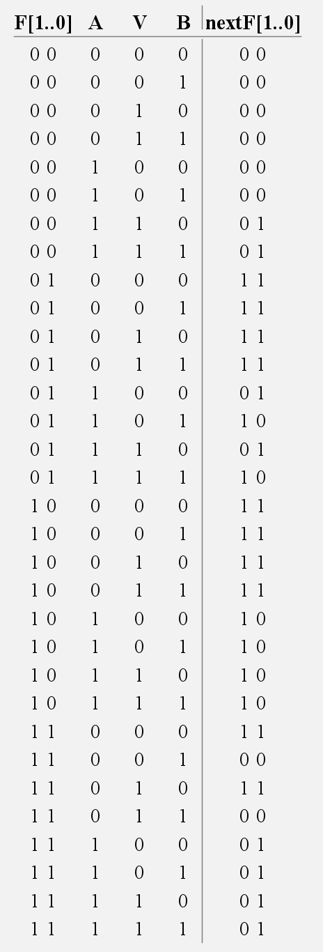
Part A: 5 State Table
| F1 | F0 | AVB | newF1 | newF0 |
|---|---|---|---|---|
| 0 | 0 | 0XX or 10X | 0 | 0 |
| 0 | 0 | 11X | 0 | 1 |
| 0 | 1 | 0XX | 1 | 1 |
| 0 | 1 | 1X0 | 0 | 1 |
| 0 | 1 | 1X1 | 1 | 0 |
| 1 | 0 | 1XX | 1 | 0 |
| 1 | 0 | 0XX | 1 | 1 |
| 1 | 1 | 0X0 | 1 | 1 |
| 1 | 1 | 1XX | 0 | 1 |
| 1 | 1 | 0X1 | 0 | 0 |
Part B
(This was when i thought it was a mealy machine)
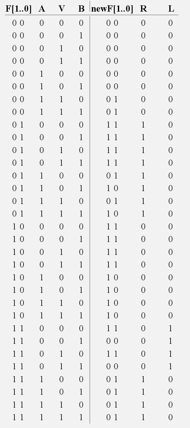
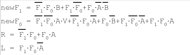
Part B for real
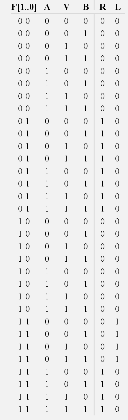
- A Moore Machine; each state determines raising, lowering, or lack thereof.
Submission
- Krish Patel | 1011078129 State transitions diagram: (separate)
State Table (Part A):
| State | Input (AVB) | Next State |
|---|---|---|
| Down | 0XX or 10X | Down |
| Down | 11X | Lifting |
| Lifting | 0XX | Lowering |
| Lifting | 1X0 | Lifting |
| Lifting | 1X1 | Up |
| Up | 1XX | Up |
| Up | 0XX | Lowering |
| Lowering | 0X0 | Lowering |
| Lowering | 1XX | Lifting |
| Lowering | 0X1 | Down |
Flipflop assignments:
| 0 | 0 | Down |
| 0 | 1 | Lifting |
| 1 | 0 | Up |
| 1 | 1 | Lowering |
| Truth table for the state logic: |
| State () | Input () | Next State () |
|---|---|---|
| 00 | 0XX | 00 |
| 00 | 10X | 00 |
| 00 | 11X | 01 |
| 01 | 0XX | 11 |
| 01 | 1X0 | 01 |
| 01 | 1X1 | 10 |
| 10 | 1XX | 10 |
| 10 | 0XX | 11 |
| 11 | 0X0 | 11 |
| 11 | 1XX | 01 |
| 11 | 0X1 | 00 |
| Truth table for the output logic |
| R | L | |
|---|---|---|
| 00 | 0 | 0 |
| 01 | 1 | 0 |
| 10 | 0 | 0 |
| 11 | 0 | 1 |