Does all the math (and not just adding!)
- The “arithmetic thing of a microprocessor” = ALU
- Also does logic operations)
- That was Lab 2
- There is no “standard” ALU. Our lab 2 ALU is just “an” ALU but different ALUs may do different things
Summary
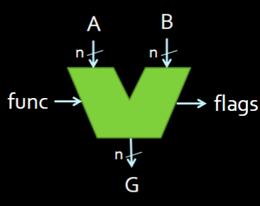
- Takes A and B inputs (of the same size ), a
func(of varying size; should be 2 bits in our ALU from lab 2). - Outputs G of size and ALU Flags
- depends on your ALU
The “control unit” is what uses the flags
- chooses if you are either doing arithmetic (i.e. adding / subtracting alongside your flags) when or logical operations when
n-bit ALU Block Diagram
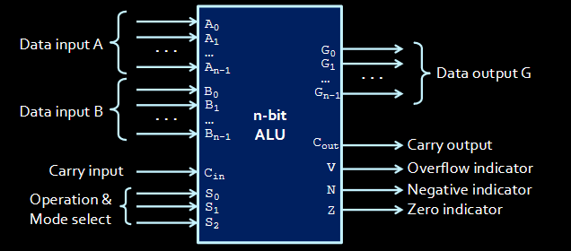
- There are
ninputs for A and B as well asnoutputs for G- todo Why not have 1 fat wire going in instead of a bunch of separate inputs? It doesn’t matter that much but it would trip me up
Making a “simple” ALU
Not a full-fledged one like a MIPS-32 ALU (that we will use after this point) Should support Arithmetic and Logical operations though
We input the 2 numbers A and B as well as S (your select bits) and
- The is the same as the one for addition / subtraction. Since the ALU has an adder, we will connect to the adder
- Used for incrementing
We output G as well as VCNZ, which are 4 “flags” where each bit has its own meaning. Extra info alongside the literal results.
- V = overflow (did the addition overflow? Is the 1?)
- C = Carry out
- We will talk abt V and C later; they are different. There are times where we discard a carry out but the result is still valid (todo )
- N = result is negative (easy to make!)
- Z = if the result is zero (if the out is ALL zeros)
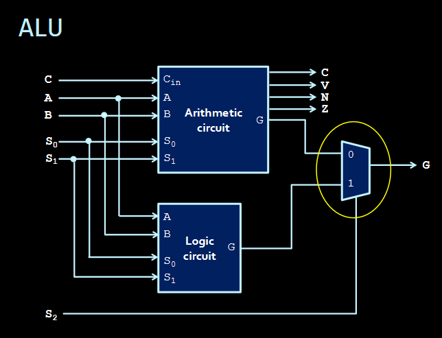
The A of the ALU (Arithmetic Component)
The ALU = A computer and logic to output more stuff with the computer The A = The part that adds depending on the select bitstodo is that right?
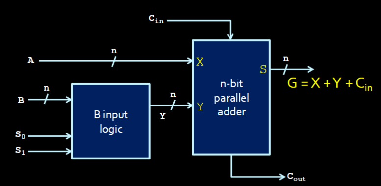 Fundamentally,
 G = X + Y + Cin
B-input logic
- Only controls the input B (A is passed into the adder verbatim always; what B is changes what kind of operation we’re doing)
- Similar to how, in just the adder, B was either itself, or inverted when subtracting.
- This “B” input logic lets us do more things with B too!
- Returns Y, which is the manipulated B
The Arithmetic Component Outputs
To summarize: G is the result of this mini component. A, Y, and is what we pass into the adder to get our result. Depending on the select bits and , Y will change.
Let’s assume . These are the possible outputs of this Arithmetic Component:
- If Y = B (i.e. if sending B through “as is” means addition):
- G = A + B
- Addition
- If Y = 111…1 (i.e. Y = -1):
- G = A - 1
- Decrement
- If
- Then B is negated but NOT its negation. Remember: to get the 2’s complement
- G = A - B - 1
- Subtraction - 1
- If
- G = A
- Transfer
As for when , well here’s a table with all the permutations:
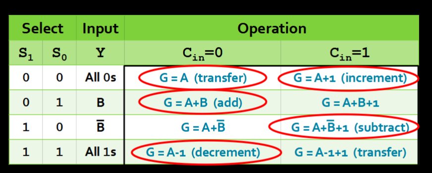
- Only 5 of them “mean” something. They are the circled ones.
The L Part of the ALU
This part returns common logical operations (in addition to the arithmetic ones from before)
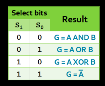
- To choose the operation depending on the select bits, we use a tried-and-true MUX!
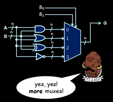
- Depending on your select bits S, we choose between the 4 logical operations and select between the operations via a MUX
- and select between the 4 logical operations
- is another bit that selects between using logic operations and arithmetic operations
- So S really carries a lot of weight here!
- So we have an “Arithmetic Circuit” and “Logic Circuit” with controlling between which two we are using.