For sequential circuits, Input + Previous State ⇒ Next State
State Diagrams
Consider a 4 bit counter. It has 8 states:
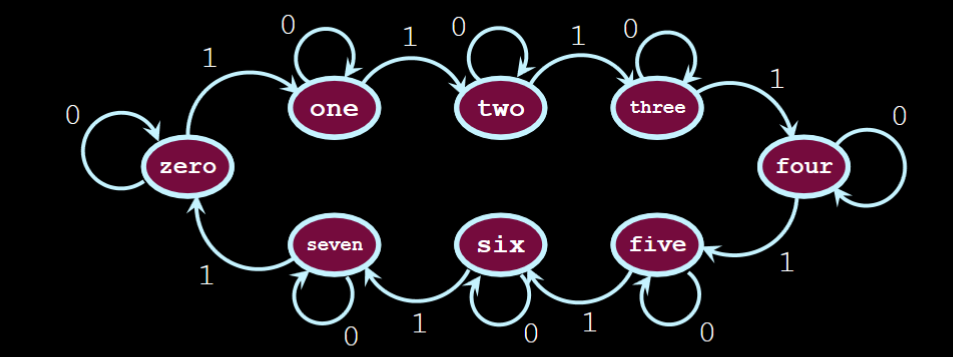
- The numbers over the arrows represent the input. When, say, a button is on its falling edge, the input will be 0, and so nothing about the counter changes. However when pressed, on its rising edge, the input is 1, and that’s when change happens.
- This diagram is very predictable; if you’re at “1” and input “1”, then your output will be “2”
State Tables
- Each “state” has a name; I like to think of them as
enums.- A binary number associates to a certain ‘state’.
- Names are surrounded by "" quotes just for clarity (some state names can be, like,
1010, which could represent the input or the actual “state we are at”)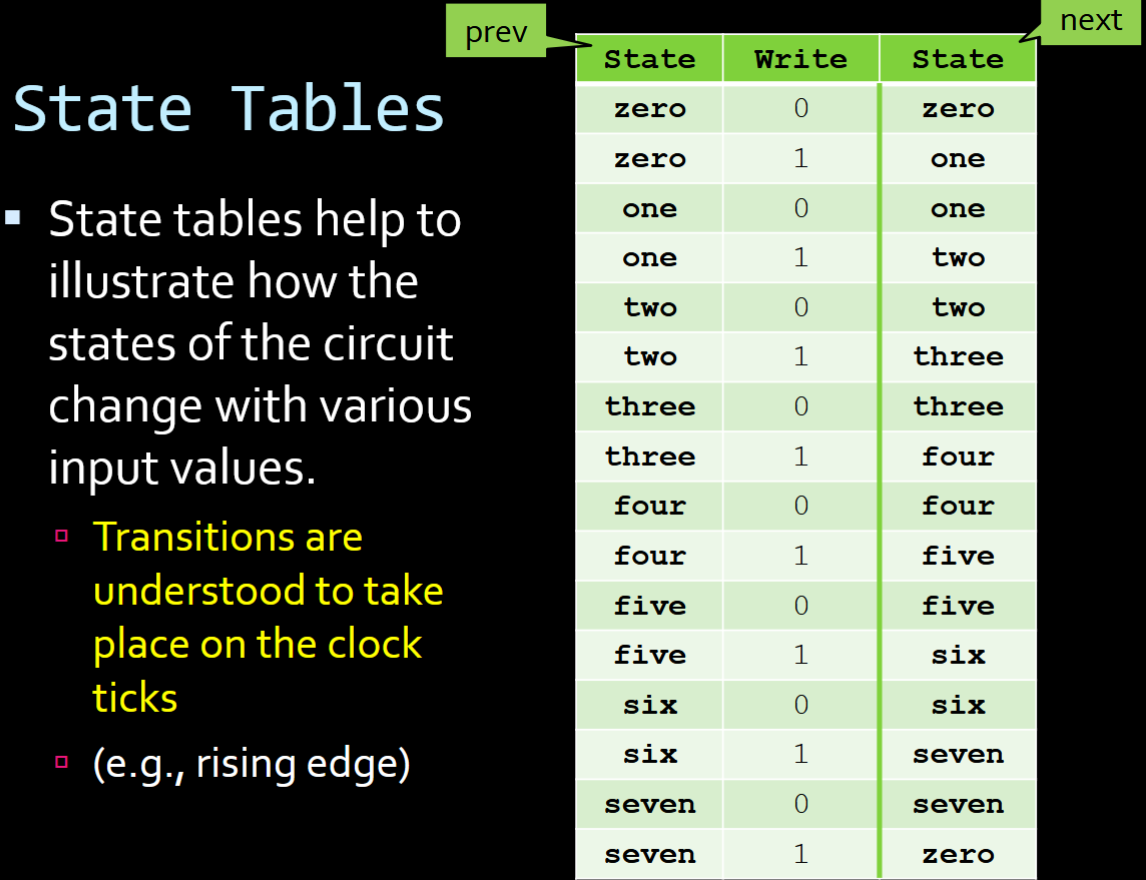
- “Write” is the input. We have 1 button as our input, so we can either have 0 or 1.
- Each switch between state should be
1input change at a time. Otherwise you might have a race condition (explained later)