This is utilized when Creating Gates as (CMOS) Circuits
You only really have to look at 1 half of the circuit to know the truth table (i.e. you can look at just the bottom half)
- Looking at the more “parallel” half is easier most of the time.
If there is connection between Y and , then the output is 1 If Y and ground are connected, then the output is 0
Examples
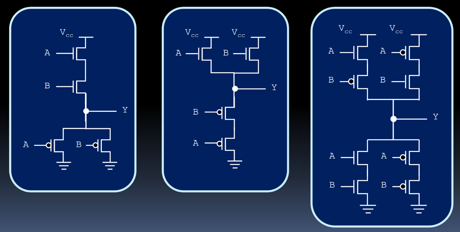
- For the first one, looking at the bottom half is easier since it’s parallel:
- When A is false OR b is false, then Y is connected to the ground.
- via De Morgan’s Law yay
- it’s an AND gate!
- When A is false OR b is false, then Y is connected to the ground.
- For the second one, looking at the top is easier:
- When A or B are true, then Y is connected to
- So it’s simply an or gate
- For the third one, we have some parallel and some series. Let’s look at that bottom half since there’s a bit more consistency between the series “sub-circuits” (?):
- When A and B are true, Y is connected to ground, or
- When A and B are false, Y is connected to ground
- Would you look at that; this looks exactly like a XOR gate!